

Evan Burton
-
Posts
4,419 -
Joined
-
Last visited
-
Days Won
16
Content Type
Profiles
Forums
Events
Store
Posts posted by Evan Burton
-
-
WAS APOLLO 14 FLAG MOVED?
No.
Firstly look at a crop of AS14-66-9277 (use hi-res images for more detail):

AS14-66-9277 (taken at GET 114:53:38)(Hi-resolution, cropped)
Now, notice some things on this and the full image:
1. The leg with the ladder on it (the west leg) is within the shadow of the LM.
2. The base of the flag is between the LM shadow and the shadow of the antenna dish. Notice how the base is much closer to the dish shadow than the LM shadow.
3. Notice the antenna dish shadow is much lighter than the LM shadow, because the dish is perferated and lets a lot of light through.
4. We cannot see the antenna dish because it is behind (i.e. north of) the LM.
Now look at a cropped image of AS14-66-9305:

AS14-66-9305 (taken at GET 114:57:20)(hi-resolution, cropped, annotated, reduced to 70% of original size)
Now notice:
1. The west leg (ladder leg) is still within shadow.
2. & 3. The base of the flag is between the LM shadow and the shadow of the dish - much closer to the dish. The shadow of the dish is hard to make out but I have put arrows to help. Look at the hi-res image to confirm this.
4. The antenna dish is now clearly visible because we are now looking at the north LM leg at the right of the dish and flag.
Additionally, have a look at this image from later on the same roll:

AS14-66-9338 (Taken at about GET 136:26)
You can see the shadow of the LM on the left, the flag, and the antenna dish shadow.
The flag has not moved
Even if it had, so what? They moved it. Does Jack mean to say that once placed into the lunar soil, a flag cannot be repositioned? Cannot be moved?
-
SPOT THE LIGHT ABOVE - additional
I also found this colour photo, Bill. Also during EVA-2.

AS12-47-6919 hi-resolution (Cropped, annotated, enlarged to 300% of original size)
I think that's the LM in the background of the visor reflection, so it may actually be part of the LM - but I don't think so. Something for you to consider in any case.
-
IMPOSSIBLE PHOTOGRAPHY
Jack says:
"Additionally, a circular halo is not a true photographic result of pointing the camera directly at the sun"
Jack's so-called 'expertise' (or rather the lack of it) becomes apparent when people around the world disagree with Jack.

From http://www.sundog.clara.co.uk/halo/circular.htm

From http://www.robratkowski.com/oddsends/
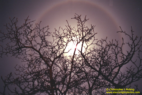
From http://www.southernskyphoto.com/moon/halo.htm
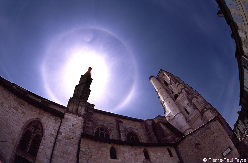
From http://ppfeyte.free.fr/photometeores/photometeore19.htm

From http://ecf.hq.eso.org/~rfosbury/home/natur...aros/paros.html
They are all obviously "in on it" and have faked these images for the sole purpose of discrediting Jack's work.
Do a google search for "lens flare" or "circular halo", select images, and see what you come up with yourself.
Now, the other point. It can be filled in "so perfectly" because:
1. Light is reflecting off the astronaut's suit and providing additional light; and
2. The original image has probably been "pushed" during development in order to show greater detail.
Light reflecting off suits and the lunar surface is has been previously explained.
This site:
http://www.iangoddard.net/moon01.htm
explains the reflected light and other so-called anomolies.
Edited to add:
I forgot the editor's comments. They say:
Editor's Note: Exactly the same conclusion was reached by Bennet and Percy in Dark Moon: Apollo and the Whistle-Blowers.So they have also reached the incorrect conclusion, and are equally displaying their shortcomings in photography.
-
DOUBLE CROSSED DURING APOLLO 14?
The image Jack refers to is from the GRIN server:
http://grin.hq.nasa.gov/ABSTRACTS/GPN-2000-001144.html
They use different file ID numbers on their own server, but as the link aboves shows, they always give the original photo ID.
As far as the "overlay lifting" is concerned, we proved Jack was wrong about that on the previous page. Hasselblad have told us that it is a reflection from the reseau plate.
-
SPOT THE LIGHT ABOVE
I have to disagree with Bill on this; I believe it is simply a smudge on Conrad's helmet.
The image shown is AS12-48-7071. Here is a crop of the hi-resolution version, showing the area of interest:

Crop of AS12-48-7071 (hi resolution) enlarged to 300% of original size
Now lets have a look at some other shots of Conrad during EVA-2:

Crop of AS12-48-7134 (hi-resolution) enlarged to 500% of original size

Crop of AS12-48-7133 (hi-resolution) enlarged to 500% of original size

Crop of AS12-48-7074 (hi-resolution) enlarged to 500% of original size
The smudge appears in all of them. It's only really noticable when sunlight is stiking the front of Conrad at the right angle.
-
IN CAMERA RETICULES?
Jack correctly labels the left image as AS12-487135. The right image is labelled as12-GPN-2000-001316. That is technically correct, because that is the file number for that image on a different NASA server. If you have a look at this page, you’ll see that is the number given to it by the Great Images in NASA (GRIN) server; they do correctly identify the image as being AS12-48-7136 though.
That leads us to a small point to note; the image Jack has used is from the GRIN server and may be enhanced because it is like a PR library. I’m not saying it IS enhanced or altered, just that it may be. For research purposes, you should use the scans available from the ALSJ or Kipp Teague’s Project Apollo Image Gallery. They use scans from original sources.
The image Jack showed, however, was the GRIN image so that’s the one we should examine. I’ll use it’s official NASA designation but make it clear when rfering to the GRIN image or the ALSJ source. That being said, the two images are:
AS12-48-7135 and AS12-48-7136.
They were taken right after each other, by Pete Conrad. The astronaut is Al Bean. The GRIN text says that it was Al who took the shots, but they are wrong.
From ALSJ:
134:16:43 Bean: (Chuckling) You got a calibrated eye, huh? (Pause)[Al's pictures of Pete are AS12-48- 7133, and 7134. Patrick Vantuyne as created a red-blue anaglyph ( 393k.]
134:16:48 Conrad: Trouble with that camera is, if it's not right on the money, it's out of focus.
134:16:52 Bean: Okay.
134:16:54 Conrad: Okay, Houston. I'm jiggling it (as shown in 7134). The Surveyor is firmly planted here; that's no problem. Okay, Al. We're ready to start getting the TV camera.
134:17:03 Bean: Okay.
[After they finish taking each other's pictures, they will remove some Surveyor parts for placement in a vacuum can and, then, the Surveyor's TV camera for return to Earth. The fact that the Surveyor is firmly planted means that it's not likely to start sliding farther into the crater as they work around it.]
134:17:09 Conrad: Now ...
134:17:10 Bean: Hey, Pete, you want to do something for me first?
134:17:11 Conrad: Yes, sir. Okay. I sure will. (Long Pause)
[They are trading places so that Pete can take a picture of Al with the Surveyor.]
134:17:30 Conrad: I'll be darned. (Pause) All soft dirt. (Pause) Okay, (give me) a big smile.
134:17:42 Bean: Okay.
[Pete's pictures of Al are AS12-48- 7135 and 7136.]
Compare the two images and you'll see that Pete moved slightly between shots, thus accounting for the movement of the reticules. Al remained almost perfectly still, so he looks almost exactly the same in the two images.

AS12-48-7135

AS12-48-7136 (from GRIN server, SMALL size)
The difference between the two images has been highlighted excellently in this comparison / composite image created by Data Cable of the Bad Astronomy / Universe Today forum:
Composite created by Data Cable
Take a good, close look at the areas indicated by the red markings. Pay particular attention to the shadow cast by Al's right arm onto Surveyor, and the shadow cast by Surveyor onto Al's leg. This shows the slight movement between the shots.
Also notice how the Surveyor leg is much closer to the bottom of the frame in 7136, then look at the fiducials. They are correctly placed for each frame.
-
No, I didn't think Jack would try to refute this; he knows he can't. It's a double whammy for Jack there; not only is the reason for the effect given, but the method that Jack says produced the effect is actually impossible to do.
Anyway, on with the show.
-
As has been amply demonstrated, Jack will not answer any refuting of his so-called studies.
When proof contrary to his claims has been demonstrated, he ignores them.
From this I can only summise that he is either:
1) Incompetent and unable to recognise his own errors; or
2) Deluded to the point he is unwilling to admit to his own errors; or
3) Deliberately deceptive and therefore unwilling to admit his errors as it will expose his deception.
Contrast his behaviour to Bill Dines - a person who shares Jack's views and is in opposition to mine - yet willing to admit when errors are made and open to discussion on all aspects of his beliefs.
-
UPDATE ON JACK'S CLAIM OF OVERLAY LIFTING
Some of Jack's claims dealt with so far involve 'doubling' of the crosshairs. Jack claims this to be evidence of overlay lifting during the 'faking' process. The Aulis editors also back this claim.
I did something that neither Jack nor Aulis bothered to do - I contacted Hasselblad and, as the makers of the camera (and experts in photography for over 100 years), asked them if they could explain what was going on.
This is what I sent:
Hello!I have a technical question I'm hoping you might be able to answer.
In the Apollo photos taken on the Moon, you sometimes see an effect with the fiducials. It happens when the camera is pointed into a bright light (the Sun); the fiducials appear to cast a shadow. The effect can be seen in this image:
http://www.hq.nasa.gov/office/pao/History/...4-66-9305HR.jpg
I'm wondering if the extremely strong light coming in through the lens is somehow causing a reflection off the reseau plate to be bounced off the innermost lens, and reflected again onto the film? That might account for the curvature we see, and explain why when it is near the centre of the image the effect is very small. The outermost sections would be reflecting off sections of the lens with the largest curvature or angle relative to the film "normal".
I would appreciate any assistance you can give in this matter.
I received the following reply:
Hello Mr. Burton,The effect you can see is caused by interference from the reseau plate. The image of the sun on the film is partly reflected and acts as a secondary strong light source. The reseau plate is a 4 mm thick glass plate and the distance between the surface facing the film and the film itself is around 0.1 mm in outer areas (less in center areas).
The strong light reflected from the film is reflected again from the reseau plate surfaces. Due to glass reflection properties (total reflection at larger incidence angles), the radius of corresponding "halo" is maximum around 7-8 mm. The shadows of the two hair crosses close to the periphery of the halo are caused by two types of reflections from the reseau plate.
The OK looking cross comes from two reflections in the front surface (facing the lens) and one reflection in the rear surface. The final reflex hits the hair cross at a similar angle like ordinary light and therefore the hair cross looks OK.
The skew cross comes from one reflection in the front surface with the light hitting the hair cross coming at an angle not too far from the total reflection angle of around 42 degrees. Outgoing light has a large exit angle (more than 60 degrees probably) making the offset you see in the image. You can also see that the skew line looks to be pointing at the halo center, which indicates where the original light comes from.
Hope that above explanation is understandable. Please come back for possible additional clarification.
Best regards
VICTOR HASSELBLAD AB
Erland Pettersson
Product Manager Camera Systems
Tel. +46 31 102450
Fax. +46 31 135074
Now, will Jack attempt to maintain some shred of integrity and withdraw those claims? I suspect not.
-
WRECKER ON THE MOON?
Oh come on, Jack!
"I noticed what looked like the rear of a pickup truck..."?!
"Computer image shows twin-boom government wrecker....."?!
What was the licence plate number? It looks like a giant snail to me.
Here is a link to the high-resolution scan of AS12-487091. Have a look for yourself.
All that there is are some dust spots(?) and errors from JPG compression.
See if you can find Jack's "wrecker". This is an example of where Jack's fantasies become totally absurd. He claims that NASA is conducting the worlds biggest and most involved coverup, yet people would make simple mistakes like forgetting to drive a car out of the picture.
This is simply misuse of a computer enhancement tool.
I have asked Jack the following question:
"If I contacted the makers of Photoshop, and they examined the image you used and stated that there was no object in the image and it was simply misuse of Photoshop, will you admit you are wrong about this particular claim?"
Jack REFUSES to answer this challenge.
-
LUNAR MODULE AND DISH CHANGE SIDES
This simply misidentifying the orientation of the LM, a mistake Jack makes many times in his studies. He has also misidentified Pete Conrad as Al Bean in AS12-47-6988, once again indicating a lack of research.
Let's just quickly review our orientation when refering to the LM.
The side of the LM with the hatch, porch and ladder on the leg is known as WEST.
If we are looking above the LM, the side to the right of the ladder is NORTH, the side to left of the ladder is SOUTH. Directly opposite the leg with the ladder is EAST.
The LM will always try to land downsun, so the sun is always going to be towards the EAST of the LM. The east side of the ascent stage is the one where that big flat side is.
Okay? If unsure, look at the diagrammes in "LM OFF BY 90 DEGREES" a few posts ago.
If we look at AS12-47-6988, we are looking at the NORTH side of the LM. The flat side is out of frame to the left, and the side with the ladder and hatch (west) is to the right.

AS12-47-6988
Pete Conrad is working at the MESA. We can see the 'north' leg of the LM pointed towards the camera. To the right of Conrad, you can see the ladder. That's the WEST side of the LM. You can see the S-Band antenna pointing to roughly north-east. You can see it is located to the north-west of the LM.
We can also see that the sun is coming from the left of the image - that is from the EAST.
We have seen the same scenes in other images, like the B&W images taken from Surveyor. You can see the big flat side of the LM (east) towards us and the antenna to the right (north) of the LM.
Now lets look at AS12-48-6806.

CROPPED SECTION OF AS12-48-6806HR
Behind Bean, you can see the front of the LM (with the hatch). That's the WEST side of the LM.
To the left of the LM (i.e. to the NORTH) we can see the antenna - where it is supposed to be.
It hasn't changed sides.
Now, here is an interesting illusion, one you have seen before. Look at the direction the S-Band antenna is pointing. it looks like it it pointing to the north-west (in the previous, it was pointing north-east). You can even see a shadow.
Is this right? Well, the astronauts could have simply moved the antenna to point in a new direction - but they didn't. It's an illusion. See how the antenna appears to be pointing to the top left, and the shadow is to the top right? Think about it - if this were correct, then the sun would have to be to the northwest. If it were, then the front of the LM would be lit. If it were, at least the front-right of Al Bean would be lit - but they are not. That's because it's an illusion.
Remember the drawings where it looks like an old ladies face, but if you just alter your focus the drawing changes to a young lady? It's similar to that. The antenna is still pointing to the north-EAST, but we are looking from BEHIND the of the antenna. Because of its construction, we can almost see straight through it.
Can we check this (apart from the sun angles)? Yes. Look at the crop of AS12-48-6806HR enlarged to 380% of it's original size.

Crop of AS12-48-6806HR enlarge to 380% of original size
Notice the legs at the bottom of the antenna. Notice how they go up to the 'middle' of the dish. Notice how the view of the dish at the bottom of the dish is BLOCKED by the legs. The legs are before the dish, from our viewpoint. The dish is pointing AWAY from us.
Also note that Jack says the sun is from the left; well, not quite. If it was to the left, you wouldn't get the big sun flare in the image. The sun is actually to the east-northeast of the LM.
Once again, Jack is wrong.
-
ANOTHER MINIATURE STAGE SET?
No, it's not.
The two images Jack shows are AS12-48-7090 and AS12-48-7122 (Jack has accidentally mislabelled it as 1122).
So what is going on here? Is Jack right? No - it's perspective. Read about it at Clavius.org.
Reference to the contour map of Surveyor Crater shows us that the crater Jack refers to was 75m behind the Surveyor craft. When the astronauts took 7090, they were about 35m away from Surveyor, on the opposite side to the crater Jack refers to. When they took 7122, they were an estimated 5m away.
Set up your own test of this, and see the difference perspective makes.
-
SUSPECT SURVEYOR III IN SHADOW
According to the information from ALSJ, the object in image AS12-46-6740 is Surveyor. You can also see it in a few other images from EVA-1 (most notably the LM pans). AS12-46-6740 was taken at a GET of 116 hrs 22 min. When that image was taken, the sun angle was about 8 degrees above the horizon. The sun is hitting the top of the Surveyor.
When the other image of Surveyor (AS12-48-7133) was taken during EVA-2, it was a GET of 133 hrs 46 min; some 17-odd hours later. During that time, the sun has risen and is now about 17 degrees above the horizon, lighting up Surveyor and the crater.
If you look at AS12-46-6741 (GET 116hrs 22min), the edge of the shadow is just touching two small craters.
If you look at AS12-47-6948 (GET 118hrs 28min), the edge of the shadow is withdrawing into the crater, and has moved from the two small craters.
By the time EVA-2 happened, the crater was in full sunlight.
Jack also asks why they didn't take any photos from the LM to Surveyor. Generally, because that was into sun. There were some pan shots taken, but they were during EVA-1. During EVA-2, when the crater was lit, they approached from the opposite side. Here's a travers map of EVA-2:

Apollo 12 EVA-2 Travese Map (A12-S69-59538)
Once more, all logical explanations, and no anomolies.
-
IDENTICAL LUNAR MODULE - DIFFERENT SCALES
Once more, Jack tries to use distant, fuzzy images to support his statement.
The images are NOT at 90 degrees to one another. Once again, it is a matter of distance and perspective.
Look at a comparison of the hi-resolution images that Jack quotes:

Comparison / cropped AS12-48-7090 and AS12-48-7133
(Excuse my mislabeling of the image - I forgot to put the '48' into the image labels)
You can see that the positions of the flag and the S-band antenna have changed. You can also note (if you look at the hi-res images) that the grouping of three rocks in 7090, which is under the 'crosshair' and to the right of the flag, has moved to the LEFT of the flag in 7133, and just to the right of the antenna (look just above the '7133' in my label)
Once again, examine the hi-resolution images for yourself to determine the facts.
-
2 MUTUALLY EXCLUSIVE VIEWS
In the images Jack shows, the LM actually DOES get larger AS12-48-7100 - but only very slightly. Check the hi-res images, and do the measurements to confirm this - do NOT take my word for it.
The LM is on the horizon, some distance away (the distance from the LM to Surveyor was 535 feet). Moving 50 feet closer to Surveyor will only make a tiny difference the LM's apparent size. The Apollo 12 Preliminary Science Report (PDF file) will probably have a site map, showing where images were taken from. I don't have access to that right now, as it is 24Mb and I'm on dial-up. Perhaps some else can post the site map.
Try this at home. Pick a similar scene with an object on the horizon at a comparable distance to the images shown. See if you can get any appreciable change in apparent size of the far object.
As for the focus, Jack has obviously never taken a photo that has a far backround in focus. His understanding of the "rules of photography" are very flawed. It's all to do with the apature setting, the lens focal legth, and the "depth of field" (as I call it - although Craig refers to it as 'depth of focus'. Who is right? probably Craig - I use the terms taught to me).
Craig explains the depth of field on the camera in this post.
Other references are:
http://www.cs.mtu.edu/~shene/DigiCam/User-...h-of-field.html
http://www.mir.com.my/rb/photography/fotot...tmls/depth.html
http://www.azuswebworks.com/photography/dof.html
Once again, grab your camera and try it for yourself. See who is right, Jack or Craig.
-
John Simpkin has kindly replied to my query and said that if I post two posts within a certain time, they get combined. That explains everything, and sorry for the combining; I'll have to slow down my trouncing of Jack (especially, as you will have no doubt noticed, he does not try to defend his studies).
-
RIDDLE OF THE RETICULES 2
Please explain why the reticules are different? Certainly!
It's because there has been slight movement of the camera, and a slight change in zoom.
I've made a composite image below to highlight it. They are AS12-48-7099, and AS12-48-7100; the same images Jack is referring to.
I've tried to get the objects to line up as much as possible, but there is still some blurring (double image) because there are slight differences between the images (notice difference in horizon). I've highlighted the frame of one image so you can compare it to the frame of the other.
Unlike Jack, if you do some research you'll see what I mean. I recommend you get a copy of the images and try it yourself. You'll see that the reticules in each image are correct.

COMPOSITE IMAGE OF AS12-48-7099 AND AS12-48-7100
Also notice that 7099 shows the two larger depressions in the surface in front of Surveyor, and 7100 only has the nearest to Surveyor in the frame.
Once again, Jack's claims of "impossible" images and "identical" viewpoints are proven invalid.
-
RIDDLE OF THE RETICULES 1
I suspect what Jack has done here is used a low resultion scan from the Apollo Image Atlas.
The Atlas specifically warns:
"Because of all this processing, these catalog images should not be used for research purposes. They should only be used to select and identify images for use in a research project. Higher resolution products should be obtained for use in any scientific investigation(s)."
Check out the high resolution scan of AS12-47-6897 and see if there is a problem with the reticules.
There isn't. The reticules are normal.
As far as the editors comments are concerned, see here. The 'anomoly' was created by the authors themselves.
-
SUNLIGHT SWAPS SIDES DURING APOLLO 12
No, it doesn't.
Firstly, remember the LMs always landed with the sun at their 'back'. That means the eastern side of the LM (see previous post) is the side the sun is coming from.
In the top left hand image of Jack's claim (AS12-46-6749) we are looking at the northern side of the LM. The sun is coming from the east, so Jack is correct about where the sun is coming from. The S-band antenna is to the north of the LM, and the flag is to the north-west of the antenna. Have a look through various Apollo 12 lunar images to confirm the locations of the antenna and flag for yourself.
In the next image (AS12-47-6897), the sun is actually coming from the bottom left hand side of the image (east) but Jack is approximately correct with his labeling.
Now look at the WHOLE of AS12-48-7134

AS12-48-7134
(See previous posts for an enlargement and crop of this image)
We can see the eastern side of the LM, the S-band antenna to the north (right) of the LM, and the flag to the north (right) of the antenna. If the sun is shining from the right in the image, then why is the "back" (easterly) side of the LM in full sun? Why isn't half of it (the left half) in shadow? That's because the sun is actually coming from the bottom right of the image, not right (north) as Jack has labeled. The sun is coming from the east - as it has done constantly.
It's the same effect about shadow angles that has been addressed in a number of other posts in this thread, with photographic evidence demonstrating the effect. Once more, it's not 'impossible' because Jack has got it wrong.
ONE MORE FOR THE ROAD
Jack has simply used Photoshop (or similar) beyond it's limits to "create" things that aren't there. He has exagerated what might be minor imperfections in the scan, created some ill-defined blurry shapes, and then claims to be able to identify them as a "truck" and a "spare LM".
Look at the high resolution image yourself and see if you can spot Jack's fictious "truck" and "spare LM".
This example by Jack is at best incompetence, at worst deceit.
Hmmm - something strange is happening.
Seperate posts are being 'combined'. For some reason, there are two examples above of a post being appended to another. I edited the post to take it out but it just jumps straight back in.
No matter, it doesn't affect the content.
Please excuse the board's quirky behaviour!
-
LEM LOCATION IS OFF BY 90 DEGREES
I'm not exactly sure what Jack is trying to say here, but if I understand him correctly he is refering to the location of the antenna. Based on that assumption, I'll show he is wrong.
First, let's get our positions from the LM correct using this diagramme:

Courtesy of the Apollo Lunar Surface Journal
Next, if we read the Apollo Lunar Surface Journal for time 115 hrs 54 mins, it says:
115:54:40 Conrad: Okay. Now, where did we all agree was the best place to deploy this S-band? Out the Y gear (that is, north), huh?
115:54:45 Bean: Yeah.
115:54:46 Conrad: A little bit further out.
115:54:47 Bean: That ought to be...Here's a good spot.
115:54:48 Conrad: Hey, I don't want to get too far away from the cable. What's the matter with right here?
115:54:52 Bean: That's a good place.
[Pete is deploying the S-Band antenna, which needs to be pointed at Earth within just a few degrees. Because Earth is nearly overhead and it is difficult to bend back in the suit, finding it is a chore. The final orientation of the antenna is shown in photograph AS12-47- 6981, which was taken at the end of EVA-1 at about 118:30:43. The diameter of the parabolic reflector is 3.0 meters (10 feet). Pete has the option of erecting the antenna anywhere in the northwest quadrant about 20 feet from the MESA. Because he needs a clear line-of-sight to Earth and because there is a fair-sized crater west of the LM, he will set the antenna up north a little west of the plus-Y footpad. See, also, photo AS12-46- 6867, which was taken from Al's window before the start of EVA-2. It shows the S-Band shadow and the aforementioned crater.]
If we look at a composite image of AS12-46-6749 and AS12-46-6750, we can see that the antenna appears slightly to the right of the LM in the image. In actual fact the antenna is closer to the camera than the LM; about 20 feet closer, according to the ALSJ. We are looking at the Y= axis (north) leg almost straight on. Notice where the "point" of the S-band antenna is going - about up to the 11 o'clock position. It's pointing in a northeasterly direction (reference the LM).

COMPOSITE OF AS12-46-6749 and AS12-46-6750
In the (unlabeled) B&W image to the middle-right of Jack's post, we can see we are looking at the 'black bulge' on the LM almost directly on. So the photographer is north-east of the LM, and we are LOOKING south-west.
Notice in that image that the S-band antenna "point" is going straight up, so it's pointing north-east, matching our estimate in the previous colour image.
In the next image (Jack's AS12-48-7100) we are looking at the "back" of the LM. You can see the Z- axis leg isn't quite pointing at us; it's slightly to the right. That means we are looking at the LM in a west-northwestly direction, and the photographer (and Surveyor) are in an in an east-southeasterly direction FROM the LM. You can see the "point" of the antenna is now going up to the 1 o'clock position, still matching our estimate of pointing in northeasterly direction.

AS12-48-7100 (Cropped, annotated)
Everything matches the change in angle, including the LM.
-
POSSIBLE OR IMPOSSIBLE?
Firstly, the two images Jack has shown are AS12-46-6749 (colour) and AS12-48-7152 (B&W).
To begin, let's see the ORIGINAL images:

AS12-46-6749

AS12-48-7152
One close up, and one REALLY far away. With the B&W image, we are trying to judge shadows from a great distance at a very low angle. This can be misleading.
What we have to do is look at shadows that are on vertical surfaces, since our error in perception will be minimised.
Next, Jack says that they are taken "from approximately the same viewpoint".
I would disagree. Apart from the HUGE difference in distance between photographer and the LM, there is about a difference of 45 degrees in azimuth between the images.
In 6749, we are looking at the LM "side on" (they actually have names like X+ axis, X- axis, Z+ axis, Z- axis, etc, but I'll try to keep it simple).
In 6749, the 'back' of the LM ascent stage (the big flat plate) is side on to us. We have an LM leg pointing roughly at us, with the US flag to it's right, and a black section with a bulge to the left. The astronaut is standing in front of the LM leg that has the ladder on it.
In 7152, the black section with the bulge is nearly pointing at us - it's actually pointing slightly to our right. We can clearly see the 'back' on the LM ascent stage (the flat plate again). The leg with the ladder is not visible - it's hidden by the LM.
So take about a 45 degree difference in the viewpoints. That is NOT "approximately the same viewpoint".
Now let's see what we can tell about the shadows.

AS12-48-7152 (Enlarged, cropped, annotated)
You can see the shadow on the DPS engine bell.
1. The shadow starts low on the left, roughly even with the left hand LM leg.
2. The shadow reaches it's zenith under the 'black bulge' on the LM descent stage.
3. The shadow drops off again on the right, roughly even with the right hand leg.
4. There is a shadow cast by the thruster onto the side of the LM ascent stage (the "polygon")
Now lets look at AS12-46-6749, the colour image:

AS12-46-6749 (Cropped, annotated)
Let's revisit those points:
1. Not visible in this image. That's correct, because we have moved 45 degrees to the right, and that portion of the engine bell isn't visible.
2. The shadow reaches it's zenith, now to the RIGHT the 'black bulge'. Remember, we've moved 45 degrees to the right so from our new viewpoint, the 'black bulge' has moved left.
3. The shadow drops off near the LM leg. Notice how you can see a clear line where the engine bell moves into total shadow.
4. There is a shadow cast by the thruster on the side of the LM ascent stage (the "polygon").
It should also be mentioned that AS12-46-6749 was taken at a Ground Elapsed Time (GET) of 116 hr 24 mins and AS12-48-7152 at a GET of 134 hrs 45 mins - a difference of over 18 hours!
During that time the sun angle has changed, rising by over 9 degrees (0.52 degrees per hour). That accounts for why the shadow is higher on the bell in 6749 than in 7152.
So everything has remained correct. No shadow anomalies. All is in order, and once again Jack is wrong.
************************************
LIGHT DIRECTION ANOMOLIES
This effect has been addressed previously in this thread (page 3), with a number of images demonstrating the effect. Shadows do NOT have to be parallel.
Remember to try this yourself; pick early morning or late afternoon (when the shadows will be long).
-
USE OF TRIPOD ON MOON 2
Once more Jack shows only what he wants you to see, and gives you both misinformation and misdirection.
1. It is NOT impossible to have nearly (or indeed) identical images without use of a tripod. It simply takes a steady pose.
2. Jack shows you only cropped images - which themselves show differences in lighting indicating slight movement!
The images are AS12-46-6726 and AS12-46-6727, NOT 5726 and 5727 as Jack has said. Once more, I presume this is just another error on Jacks part.
The same comments that apply to "use of tripod on moon 1" apply. Look at the FULL images.
Now, take a look at the original images which I have scaled to 50% for ease of viewing. If you want the originals, look at AS12-46-6726 and AS12-46-6727.

AS12-46-6726 scaled to 50% of original

AS12-46-6727 scaled to 50% of original
As you can see, there is clear movement between the images. 6726 had a sun flare at the left hand side, and you can still see the "stars" of the US flag on the side of the LM. 6727 has NO sun flare, and the 'stars" of the US flag are out of frame.
-
WHY ASTRONAUTS SHADOWS ARE ANOMALOUS
This simply illustrates Jack's lack of experience with using a camera (if I understand what Jack is trying to say - a difficult task at times).
There is nothing wrong with any of the images (none of which are labeled with their ID number).
Jack seems to be saying that the bottom of the shadow of the photographer must be in the bottom centre of the image.
UTTER TOSH AND TWADLE!
I won't bother to explain this to Jack.
I would simply ask anyone to go out and try this themselves.
Grab your camera (preferably digital so you can instantly see the results and not have to waste money on developing photographs).
Pick a time early morning or late afternoon, when the sun (sole lighting source) is low, so that you can get a long shadow from your body. Try to pick some terrain roughly similar to what the images show.
Position yourself so that your back is to the sun.
Aim the camera so that your (long) shadow is in the centre of the image.
Now, turn yourself slightly to the left or right, so the camera is aiming to the left or right but your shadow is still in the shot. Best of all, try to reproduce the images Jack has shown using any convenient objects you have around.
YOU MUST BE PART OF THE APOLLO CONSPIRACY!
After all, Jack says that "it's the law", right? NO. Once more, Jack is wrong.
Look at your images. They are the same as the Apollo 11 images? Yes?
Look at these images I took myself:


If Jack would like to publicly accuse me of faking these images, I would be more than willing to set up an independant verification of the reality of those images.
Shall we check to see if those images can be reproduced without modification or alteration, Jack?
-
Hmmmmmmm?
This is another example of where Jack doesn't say what he actually means. It's a common tactic; present something and then try to lead the viewer to your conclusion by intimating something without actually saying it.
What Jack is trying to say - in my opinion - is that because there was a model of the CSM over a model of the moon, the image of the actual CSM over the actual moon must be suspect. There is nothing of the sort. Images were produced to show what the mission would look like; images were produced to help the astronauts train, to show them what they could expect to see.
Notice that the model of the CSM looks different from the actual image of a CSM in lunar orbit (Which is AS17-145-22261, a detail I am sure that Jack simply forgot to add).
Have you never seen an artists impression of what a new aircraft may look like? Have you never seen (prior to computer generated graphics - CGI) models being used in the training of flight crews?
Contrary to what Jack intimates, without the production of models and simulation, Apollo would have been likely to fail without these training aids.


Jack White's Aulis "Apollo Hoax" Investigation - A Rebuttal
in The Apollo Moon Landings
Posted
DIVERGING SHADOW PROBLEM
Put simply, what Jack says is NOT correct. Shadows do NOT have to be parallel. See:
http://www.clavius.org/shad15.html
http://www.clavius.org/trrnshdow.html
http://www.clavius.org/a11rear.html
http://www.lunaranomalies.com/fake-moon.htm
http://www.braeunig.us/space/
http://www.badastronomy.com/bad/tv/foxapollo.html#parallel
http://www3.telus.net/summa/moonshot/index.htm
Similarly for the editor's comments: Once again, David Percy is incorrect. I need to confirm this, but I believe the Aulis website is actually run by Percy / Bennett. If this is correct, why don't they mention this when refering to their book during Jack's studies? If they do run the website, why do they refer to themselves and their book as though they are totally seperate people? If this information is correct, do they have something to hide?