

Evan Burton
-
Posts
4,419 -
Joined
-
Last visited
-
Days Won
16
Content Type
Profiles
Forums
Events
Store
Posts posted by Evan Burton
-
-
HATCH ANOMOLIES 7 (Yet another shadow / LM exterior colouring)
Jack's hatch fixation continues.
Jack claims (yet again) there is a 'shadow' across the hatch - but this time it is on Apollo 17, specifically AS17-140-21370. He doesn't actually SAY what might be causing a shadow; I presume that it is meant to be self-evident.
No, it's not self evident and no, it's not a shadow. Jack is wrong (again).
Still, in fairness and to maintain credibility, let's examine the claim.
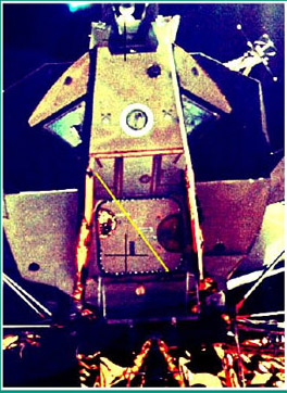
Firstly, here is a crop of the enhanced image Jack made by changing the intensity of the RGB colour:

Notice the yellow line Jack has drawn in, to illustrate where the 'shadow' line is, and thus the 'tonal difference'. The 'darker' area (i.e. shadow) is indicated by the bottom / left side of the yellow line. That means the 'additional lighting' would be coming from the left hand side of the LM.
For a start, look at the left hand side of the forward face of the LM (what jack has labelled as 'A' in his images under the hatch images. Look at the right of that face, immediately to the left of the hatchway structure. In both the images Jack presents, there is a darker portion. I've highlighted it here:

Now, if there is additional lighting from the left hand side of the LM, why isn't this area being lit? That's because Jack is wrong.
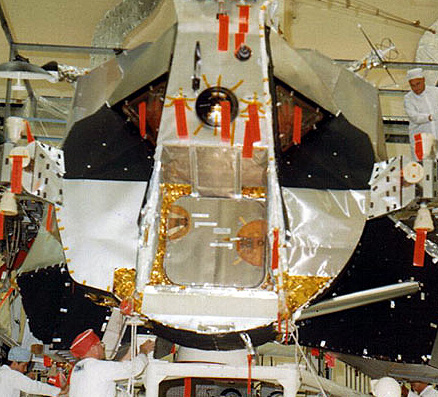
Let's look at that same 'shadow' portion again, but first, look at how the LM hatchway looked:

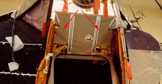
LM-9 at Kennedy Space Centre
Notice how the hatchway extends out at the top of the hatch area, and curves down to meet the lip of the hatch at the bottom (indicated by red arrows)?
So if Jack's 'shadow' starts at the top left hand corner of the LM hatch, and the hatch extends out at the top, any light source would need to be pointing directly at the top of the hatch area in order that it does NOT cast at shadow at the top left hand side.
The bottom of Jack's shadow extends all the way across the hatch to the bottom right hand corner. The structure at the left of the hatch curves down to meet the hatch area here. Therefore, to have a shadow caused by this structure go all the way across the hatch to the right hand side, the light source would need to be on the FAR left of the LM, at 90 degrees to the previous 'light source'.
It's impossible! A shadow cannot be cast as described, because the light positions are in at least two different locations.
Don't take my word for this; construct a little cardboard model that roughly approximates the hatch structure. Try and get a light source to create the 'shadow' that Jack says is there.
Next, let's examine Jack's claim about the 'bad lighting' on Apollo 11.

Jack compares images of the LM front - AS17-140-21370 on the left, and AS11-44-6574 on the right. He points to Apollo 11's LM front area (labeled 'A') being darker than the right (labeled 'B') and says that it is the result of 'bad lighting'. He says that the black area 'A' in AS11-44-6574 should be the same as the grey area labeled 'A' in AS17-140-21370.
WRONG!!! Once more Jack demonstrates his lack of research in this area.
Let's look at some images of the Apollo 11 LM:

LM-5 (Apollo 11) during final assembly (AP11-S69-19644)

LM-5 (Apollo 11) inflight (AS11-44-6574)

LM-5 (Apollo 11) ascent stage just prior to re-docking with the CSM (AS11-44-6642)
It was the way LM-5 looked. As I have said previously, not all LMs looked the same. So, once more and with an unbroken record - JACK IS WRONG!
-
Jack White (AM)
Photoanalyst
Should that be "Claims to be a Photoanalyst'? Far more accurate...
-
HATCH ANOMOLIES 6 (Apollo 15 / Apollo 16)
Apollo 15
It appears that Jack now has a fixation on the LM Egress Hatch. Jack has said in this study:
”No photos exist of the (APOLLO 15) door” and
”… did not take a single photo of the front of the LEM (sic)”
This is why I say to everyone to do their own research, and not take anyone’s word on a matter. Once more, Jack is wrong:

Apollo 15 LM during LRV check fit (AP15-KSC-71P-282)
Link to hi-resolution copy of AS15-86-11598

Apollo 15 LM during rendezvous (AS15-96-13040)
Next, Jack asks why no photos were taken of the LRV being unloaded. That’s quite simple – it was a two-person job to unload.
ALSJ:
[After he gets the aft lanyard, Jim drapes it over the secondary strut and hops over to the MESA to get the CDR Hasselblad camera. As per LMP-4 and LMP-5, Jim is scheduled to get the CDR camera off the MESA after the Rover deployment but, apparently, wants to try to get some pictures of the deployment. However, as we will hear in a few moments, it is impossible to take pictures while keeping tension on the lanyard and walking backwards, and Jim doesn't get any pictures of the deployment. The CDR camera is stowed at the left rear of the MESA. The LMP camera is in the ETB.]
With both astronauts involved in the deployment of the LRV, there is no-one left to take photos – except the television camera.
Link to ALSJ television footage of LRV deployment.
There would have been 16mm footage also, but..
(from the ALSJ)
[Dave is now 30 minutes into the EVA and was scheduled to complete the TV operations at 29 minutes. He is only a minute or two behind schedule. However, because Dave isn't quite ready to deploy the Rover, Jim has jumped ahead to his checklist page LMP-5 and is preparing the 16-mm camera so that they can photograph the Rover deployment. Unfortunately, the 16-mm camera suffered a series of malfunctions due to improper film loading and there is very little good lunar surface film from this mission. The 16-mm camera is stowed on the right side of the MESA.]
Apollo 16
Jack points out an apparent disparity between the position of the decals on Quad IV of the LM. Yet again, Jack fails to do the research which explains this “anomoly”.
They are different decals.
The first image is AS16-118-18894, taken in orbit above the lunar surface, prior to landing, shows the decals on Quad IV.
The second image, AS16-116-18579, shows the decals in an apparently different position. That’s because they are not the same decals. The first image shows the decals on the outside of the MESA (Modularised Equipment Stowage Area) at Quad IV (to the left of the ladder if we look at the LM from the front). The second image shows the MESA deployed (i.e. folded down) and the decals we see now were previously hidden by the closed MESA. You can see here another view of Quad IV with the MESA deployed; you can see the depression on the descent stage where the MESA was folded in to.

Crop of AS16-107-17436HR
The next claim Jack makes is:
“…allegedly is the folded up LRV, but on the surface it is covered in foil.”
This claim makes little sense, because as you can see in the picture, the LRV is already unstowed and on the lunar surface!

AS16-116-18579
This claim is followed by:
”…the undisturbed soil shows the LRV was not unloaded in the vicinity.”

Crop of AS16-116-18579
Sure looks ‘disturbed’ to me! Once more, JACK IS WRONG.
-
I suspect Shanet will survive the above inference. My question, why insinuate something like that? You don't agree with Jack, that's fine -- NASA won't respond to Jack directly (or even in-directly to my knowledge) - that's fine too...
We're left with your opinion and opinions from others ALL opinions, nothing official - only the original record and the ever reliable internet cyber-warriors -- so we have discussion....
I could be wrong on this point, but I think if Jack writes a letter to NASA, he will get a reply. It might not be the reply he wants to hear, but they will reply. If they haven't replied, Jack should bring the matter up with his Federal representatives; they are a Federal organisation and have to reply even if they might think the matter is ridiculous.
Has Jack taken this further?
As far as the studies go.... there are only a couple of instances where it comes down to opinions. In most cases, Jack has made serious errors and it is not a matter of opinion.
I've said before, and I'll say again - I wish NASA would be allowed to answer Jack and his ilk directly. I would like to see ex-NASA Apollo staff bring the whole thing into court for judgement. NASA is not allowed to answer these ridiculous claims directly (e.g. the cancelled book).
-
OUR ESTEEMED COLLEAGUE JACK WHITE IS TO BE CONGRATULATED FOR HIS
COURAGE INSIGHT AND PENETRATING RATIONAL
INDUCTION OF THE PHOTOGRAPHIC RECORD..........
A THOUSAND THANKS TO THIS BRAVE PATRIOTIC AMERICAN............
HURRAY
FOR JACK WHITE
AND
JACK WHITE
HURRAY
............
Shanet - drugs are bad, okay?
-
HATCH ANOMOLIES 5 (Two-tone door, reticules)
Once more with the hatch! It was a design feature. The fact that it appears slightly different in AS12-46-6728 does not mean anything at all, lighting effects can alter the way it appears. If Jack can provide evidence that it was NOT like that before launch, then he should produce it.
Then Jack points out that Apollo 14 did NOT have a two-tone hatch. For once, Jack is right. As previously mentioned in my other posts, the LMs don't always look the same. Improvements are added, if time permits.
Reading Table 1 of NASA Technical Note D-7084 (Apollo Experience Report - Lunar Module Structural Subsystem), it notes that the thermal shield on the forward hatch (which is NOT 'painted on', by the way) on LM-6 (Apollo 12) was torn by the astronaut's PLSS backpack during egress / ingress and was replaced by a redesigned thermal shield. That's why LM-8's egress hatch is one colour, rather than the two-tone of previous LMs.
Then Jack raises, once again, the effects of lens flare on the camera and attempts to use it as evidence of fakery. He shows a crop of AS14-66-9306. He says there is a prismatic effect "of unknown cause" and then points to the crosshair 'lifting effect', claiming it is a fake added in a darkroom overlay.
Firstly, take a look at the FULL image AS14-66-9306:

AS14-66-9306
What's that up in the top left hand corner of the LM? Yes, it's the sun. The rainbow is caused by a lens flare. You will see it in many Apollo images. You'll see in many images taken in space. And yes, you'll also see it in many images taken right here on Earth:


Perhaps Jack, as an expert photographer, should take a refresher course in lens flare:
http://www.cambridgeincolour.com/tutorials/lens-flare.htm
http://www.clavius.org/lensflare.html
http://www.vanwalree.com/optics/flare.html
Next, Jack talks about crosshairs, claiming that they are added by the darkroom wizards with an overlay.
Why? If you are faking the image, why not simply organise the modification necessary to the image, then shoot it with a reseau-plate fitted camera? You'd get perfect crosshairs every time.
How did this effect, which appears in MANY Apollo images, get past all the QC inspectors? Jack's standard answer will be "whistleblowers" - but he cannot offer any proof of this.
Jack says that it's from an overlay - but fellow forum member, Craig Lamson (who I believe is a professional photographer) says that is impossible to do the way Jack suggests. In the previous incarnation of this rebuttal, he said:
The theory Jack suggests is not possible. Light and shadow from the copy process will not act like Jack suggests. In short he cant do it. I challenge him to try and create a similar result using his equipment and a simple overlay. He wont need any special equipment, just a digital camera, a tripod, and a two lights (desk lamps or those clip on worklights that cost 4 bucks will work just fine). Make a transparent overlay with some crosshairs on his inkjet printer and do the test. Prove it can be done. This is not rocket science and Jack CLAIMS to be a photography expert. Any photo expert worth his salt could do this test with half of his brain tied behind his back. Come on Jack show us some of that skill you profess to have...do the test...prove your point...for once.Can Jack demonstrate this effect using his method? If he can, let him post the results here for all to see.
Finally, what IS causing that effect?
Short answer - I don't really know.
I have noticed that they always occur around a sun flare, and only around the flare.
Have a look at the hires image of AS14-66-9306. You see the effect around the flare; all the other fiducials (crosshairs) are normal. Also notice that the you see one 'normal' set of fiducials, and the second set of fiducials curved away from the first, each one moving AWAY from the sun flare - except the ones nearest the centre of the grid and away from the sun.
Based on this observation, I've got a theory. The professional photographers can pass judgement on it, because I don't have the expertise to really say if it's right or not; it's just a guess.
We know that the reseau plate with the fiducials on it is placed up against the film.
I wondering if the extremely strong light coming in through the lens is somehow causing a reflection off the reseau plate to be bounced off the innermost lens, and reflected again onto the film? That might account for the curvature we see, and explain why when it is near the centre of the image the effect is very small. The outermost sections would be reflecting off sections of the lens with the largest curvature or angle relative to the film "normal".
Just a guess.
*****************************
EDITED 15 FEB 06 TO ADD:
I contacted Hasselblad to ask, as the makers of the camera and with over 100 years of photographic experience, if they could answer the question of the reticules. They replied:
Hello Mr. Burton,The effect you can see is caused by interference from the reseau plate. The image of the sun on the film is partly reflected and acts as a secondary strong light source. The reseau plate is a 4 mm thick glass plate and the distance between the surface facing the film and the film itself is around 0.1 mm in outer areas (less in center areas).
The strong light reflected from the film is reflected again from the reseau plate surfaces. Due to glass reflection properties (total reflection at larger incidence angles), the radius of corresponding "halo" is maximum around 7-8 mm. The shadows of the two hair crosses close to the periphery of the halo are caused by two types of reflections from the reseau plate.
The OK looking cross comes from two reflections in the front surface (facing the lens) and one reflection in the rear surface. The final reflex hits the hair cross at a similar angle like ordinary light and therefore the hair cross looks OK.
The skew cross comes from one reflection in the front surface with the light hitting the hair cross coming at an angle not too far from the total reflection angle of around 42 degrees. Outgoing light has a large exit angle (more than 60 degrees probably) making the offset you see in the image. You can also see that the skew line looks to be pointing at the halo center, which indicates where the original light comes from.
Hope that above explanation is understandable. Please come back for possible additional clarification.
Best regards
VICTOR HASSELBLAD AB
Erland Pettersson
Product Manager Camera Systems
Tel. +46 31 102450
Fax. +46 31 135074
This is conclusive proof that Jack is wrong.
-
HATCH ANOMOLIES 3 & 4 (Cross lighting)
I'll combine these two because we are talking about the same area. Jack makes reference to "Apollogists" pointing out his errors; I suspect I am that person. I contacted Aulis and pointed out that what Jack had called a 'shadow across the hatch door' was in fact it's normal colouring. I presented images which proved this. Aulis withdrew Jack's original claim, but have let him slip it back in with all the revisions he was forced to do. Keep that in mind when you consider the credibility of Aulis.
Jack originally said there is a shadow across the LM hatch, caused by the 'wing' on the 'egress door', indicating 'lighting from the left'. In his revised claim, Jack subtly tries once again to say it's a shadow by once more refering to it as 'cross lighting' and saying that looks were not a part of the LM design. Looks did not play a part in the LM design; that much is true. So what is Jack actually trying to say?
In my opinion, he is making two claims:
1. Despite the photographic evidence, the hatch really wasn't two-toned (THE HATCH); and
2. There is an unexplained shadow on the ceiling in the images (THE SHADOW).
Let's look at each claim.
THE HATCH
Jack originally refered to AS11-40-5868 when making the 'cross lighting' claim. I pointed out the hatch looked the same in AS11-44-6574 and AS11-44-6598, also showing a cropped & enlarged section of AS11-44-6598. In his revision Jack says he finds it incredible that the hatch should look this way, as 'looks' were not part of the design. Looks are not part of the design, but functionality and design defect rectification are. It's worth discussing a bit of LM background here. Not all LMs are the same. Some were built for test purposes only; these were known LTAs (LM Test Article). The first of the 'true' LMs was LM-1, which flew on the unmanned Apollo 5 for it's initial testing. LM-2 never flew. LM-3 was used on Apollo 9, LM-4 on Apollo 10, and LM-5 on Apollo 11. Later LMs (for the 'J' series missions) had stowage for the LRV, improved life support systems for longer duration lunar stays, etc. As the LMs were built, improvements and weight saving modifications were incorporated into the design, often from experience with a previous LM. LM-1 seemed to be leaky and it's descent stage fibreglass thermal shield came loose, requiring a change to the fastening assembly. LM-3 had a descent stage propellant tank contact the upper deck during the S-IC stage engine cutoff; this required a larger opening in the deck. It's forward hatch also suffered binding from the micrometeorite shield and thermal blankets, which required the shield to be extended and the blanket taped. All these were incorporated on LM-5. When building them, though, you can't always incorporate improved design features into all the LMs. At a certain stage you have to 'freeze' the design otherwise it's construction will be continually delayed trying to incorporate the improvements. Of course, any critical flaws would be corrected, but 'nice to have' improvements would be incorporated on later craft.
What this means is that the earlier LMs sometimes looked a little different to later LMs.
This is how the later LM egress hatch looked:

LM-8 Egress Hatch (Courtesy of www.myspacemuseum.com)
Notice in the middle of the hatch you can see a line and some rivets, indicating that the outer covering of the hatch was constructed in two sections - right at the point where the "shadow" appears in the LM-5 images.
What about the 'two-tone' hatch - are there any other examples? Well, with a little research I found these:

LM-3 hatch during checkout (crop from AP9-S68-36625)

LM-4 inflight (crop and enlargement from AS10-34-5091)

LM-4 inflight (crop from AS10-34-5116)
So, as you can see, it is simply the way the hatch looked. It is not a 'cross lighting' effect, even if Jack fails to understand that.
THE SHADOW
Now we have demonstrated that it is not a shadow across the egress hatch, what about the other "anomoly"? What is it? Simply put, it is a slight bulge in the panelling. It can be seen in the following images:

Crop of AS11-40-5862HR

Crop of AP11-S69-19644HR (LM-5 during checkout)

Crop of AS11-40-5863HR

Crop of AS11-40-5867HR

Crop and enlargement of AS11-44-6574
Once again, Jack has made basic errors and is wrong.
-
HATCH ANOMOLIES 2 (Little man, big door / Big man, little door)
In this 'study' Jack says:
"A tiny kneeling man with no lower legs is seen with butt and tiny backpack at opening of Eagle egress hatch. Being this close to edge of door, his feet and legs should be sticking out of door."
Well, getting out of the LM wearing a PLSS backpack was certainly a tight fit, no doubt about that. Reference to the ALSJ shows that Buzz Aldrin said during debriefing:
[Aldrin, from the 1969 Technical Debrief - "The hatch moved inward very easily. As I faced the hatch, I moved the (spare, non-EVA Hasselblad) camera from its position on the right side (the CDR's side) of the floor, up onto the Z-27 bulkhead (at the aft of the cabin). (In getting in) I had very little difficulty, again using the same technique that Neil used (at the start of the EVA when he went part way out and then tested his ability to re-enter). About halfway in, make a concerted effort to arch your back to keep the PLSS down by keeping your belly down against the floor. This affords you the least profile going in. There didn't seem to be any exertion at all associated with raising yourself up and transitioning to a point where you can bring your knees on inside the cockpit, and then moving from a kneeling (position) to an upright position. It all seemed to work quite smoothly. When there is a large bulk (that is, the PLSS), attached to you, you have to be careful. Once you get inside, before you start to turn around, you must make adequate allowance for all this material behind you."]
Also
109:39:57 Armstrong: Okay. Your PLSS looks like it is clearing okay. Your toes are about to come over the sill. Okay. (Pause) Now drop your PLSS down. There you go; you're clear. And laterally you're good. You've got an inch clearance on top of your PLSS.
109:40:18 Aldrin: Okay. You need a little bit of arching of the back to come down. (Garbled) How far are my feet from the edge?
109:40:27 Armstrong: Okay. You're right at the edge of the porch.
109:40:30 Aldrin: Okay. Back in (garbled) (Pause) Now a little of foot movement (garbled) porch. Little arching of the back. Helmet comes up and clears the bulkhead without any trouble at all.
109:40:48 Armstrong: Looks good. (Long Pause)
******************************
Remember that the LM hatch swung inwards, so there was room for the astronauts to kneel down without their legs going outside the hatch. As for the "tiny" man, well that's just how it appears. Notice that the size of the PLSS backpack is still in the correct proportion to the astronaut.
Jack then says:
"The bright lighting INSIDE the LEM is incredible, since it is alleged to be reflected from the lunar surface."
Not quite. Firstly, the lighting is mainly in the porch / hatch area; the interior of the LM is actually dark. Secondly, the lighting not only comes from the lunar surface, but also reflected off Armstrong's white suit. This accounts for many instances of so-called 'lighting anomolies'.
Jack continues:
"Based on the shadow on the backpack inside the door at left, the lighting is coming down from above... impossible if the light is reflected from the Moon's surface."
Once again, it is not only light reflected from the surface, but also from the EVA suits. Now let's have a look at the claim that 'lighting is coming down from above'. Here is a crop from the hi-resolution version of AS11-40-5862. Once again, the image has not been adjusted by me, and as always, download the hi-res image and examine it for yourself:

Crop of AS11-40-5862 (hi-res)
If the lighting is coming from above, there should be other shadows. Have a look and see if you can find any. Notice the LEC tether to the left of Aldrin, passing from inside the LM down to the surface. Does it cast a shadow on Aldrin? No. Have a look at the left hand side of the hatch, where the tether passes the edge of the hatch door; you can see a slight shadow being cast on the door edge - coming from the direction of Armstrong.
There are no anomolies.
-
HATCH ANOMOLIES 1 (window, 'shiny thing', distortion)
In this example, Jack portrays three sections of the images (AS11-40-5862 and AS11-40-5863) as displaying anomolous behaviour. Once again, he is wrong. The three 'anomolies' Jack has raised are:
- A black LM window in one image, and a 'blue' window showing a reflection of the lunar landscape in the other.
- What Jack calls a 'shiny thing' in one image, which is not apparent in the next image.
- Some type of distortion issue with the decal on the LM descent stage.
Let's look at each one in turn.
THE WINDOW
To me (and most other people), it is obvious that as Armstrong moved further to his right to take the second image (AS11-40-5863), the LM window is now reflecting the lunar landscape. Jack said in his 'analysis' that:
"...but the reflections should match."
I was going to draw a ray path diagramme to show how wrong Jack is. The LM windows are tilted down and outwards (to allow maximum visibility for the crew). When Armstrong moved, the reflection off the window would also change (if Jack wishes to challenge that Armstrong moved, I would be happy to take this up in a separate post). To make this diagramme, I would need accurate data for the angles at which the LM window was tilted. This is surprisingly hard to find. Short of actually going to a LM and measuring them myself, I was unsure what to do. I was looking through some shots I took from the Kennedy Space Centre (KSC), when I looked at the images I had taken of the LM on display (this is actually LM-9, a genuine LM but not flown - obviously. The Apollo 11 LM was LM-5). That's when I realised I didn't need a ray path diagramme.
I took several shots of the LM that is displayed in the Saturn V Hall at KSC, at various angles, with and without flash. The metadata tags say they were taken 22 MAY 02, but I must have set the date incorrectly. They were actually taken 23 JAN 03, with a Fuji FinePix F601 digital camera (I know this because I still have the KSC tickets, and I was back in Australia by then).
Here are some of the images I took (reduced to save space); note what you see in the LM windows for each image. Please note - THESE IMAGES HAVE NOT BEEN ALTERED IN ANY WAY FROM THE ORIGINAL, EXCEPT FOR RESIZING:


Now, here are crops of the LM windows from the original images (all at 100% of original size - no enlargement, NO ALTERATION OR ENHANCEMENT):


As you can see, the reflection changes as I move. You can see a reflection of the rear of the APOLLO 12 patch reproduction in one, black / grey in another, and a blue tinge in the other. I suspect the blue tinge has to do with the material the glass of the LM windows were constructed of, but have yet to confirm this.
THE SHINY THING
Once more, this is simply a case of part of the LM reflecting light from Armstrong's suit and the lunar surface in one image, and being hidden / not reflecting in another. As luck would have it, the angles that I took my images of the KSC LM are very similar to the Apollo images, and therefore show what is happening. Have a look at the composite image I have constructed below. If Jack would like to challenge that the images are not genuine in any way, I would be glad to publicly debate the matter. As always - DON'T TAKE WHAT I SAY AS FACT; go to KSC and take your own images. See if they match what I am saying, or if I have manipulated my images somehow.

DISTORTION
I'm not really sure what Jack is trying to say here. He admits they were taken at different angles. Jack says he"made them match by computer stretching" - perhaps Jack could expand on his issue with this - IN A PUBLIC FORUM?
I have to admit, I am very surprised that someone with Jack's experience in photography could be making such errors and demonstrating a lack of understanding of the basics in photography.
-
My statements have said you are not an aeronautical or aerospace engineer, nor are you a spacecraft designer. As far as I am aware you have no qualifications or experience in the aerospace world.
My complaints involve your inability to recognise errors that you have made using your photographic experience.
As far as photographic analysis is concerned, I'm not aware of any civil qualification with that name (though there may be). The only "professional" photo analysts or interpreters I know of are in the military or government (e.g. NPIC). Even in those case, they are specialised (i.e. trained to identify military items).
There are courses, though, that specialise in analysis or interpretation for specific fields (e.g. geology).
Aerial Photographic Interpretation
http://geoworkforce.olemiss.edu/courseoutl...1/aerphoint.pdf
http://www.geodata.soton.ac.uk/geodataweb/...oject.php&id=18
There is the American Society for Photogrammetry and Remote Sensing, who do run a number of courses and provide certification:
Certified Mapping Scientist, Remote Sensing (ASPRS)
"A professional that specializes in analysis of images acquired from aircraft, satellites or ground bases, or platforms using visual or computer-assisted technology. Analysis is used by various specialized disciplines in the study of natural resources, temporal changes, and for land use planning. They develop analytical techniques and sensor systems."
http://www.asprs.org/membership/certificat...guidelines.html
These people do actually publish a Manual of Photographic Interpretation.
There is a International Society for Stereology who are strongly into image analysis:
There are applications in the medical field:
Even in Australia!
There are a number of image interpretation software applications available (I wonder if any are freeware?).
There was an International Conference on Image Analysis and Recognition:
-
Thanks for that Len.
In my opinion, people could easily misinterpret what Jack believes because what he portrays will give another impression.
He has stated clearly in this thread, though, what his thoughts on the matter are and therefore I think the edits I made to the post are quite appropriate. They now accurately reflect Jack's stated position.
-
SMILE – YOU’RE ON CANDID CAMERA (All sections)
This series of images reminds me of Grandpa Simpson talking about some of his stories: they ramble on and on but don’t have a point to them.
There are a number of corrections, though, that need to be made to what Jack has said in them.
1. “THE APOLLO LUNAR SURFACE JOURNAL IS NASA’S OFFICIAL DOCUMENTATION OF EVERY ASTRONAUT ACTIVITY DOWN TO A FRACTION OF A SECOND” – Well no, it isn’t. The ALSJ is a private work started by an enthusiast, contributed to by a multitude of individuals, based on NASA records, subject to correction, and resides on a NASA server.
I contacted the creator of the ALSJ, Eric Jones, to confirm this. He said:
“…I completed enough of the Journal to put some on line in 1995 and, at that time, even short audio clips would have challenged most folks internet connections. Over the years, we added audio and video clips from a variety of sources. It is only in the last two or three years that we've been able to be systematic, thanks to the increasing prevalence of broadband AND the availability of high-quality digital version of the best recordings available in the archives, thanks mostly to Mark Gray at Spacecraft Films.The Journal is my own creation, with a great deal of input from a group of very talented, knowledgeable volunteers from not only the U.S. but also, Canada, Australia, the UK, France, Germany, the Netherlands, and Scandanavia. NASA's History Division hosts the Journal and has been very helpful in getting us access to such things as scans of the original film. The Apollo Lunar Surface Journal is NOT an 'official record' of Apollo.”
2. HOW POSSIBLE FOR THE UNMANNED CAMERA TO PAN, TILT, ZOOM, REFRAME? – Again, it didn’t. The clips provided on ALSJ are, as mentioned above, from a variety of sources. Sometimes these people will zoom in on sections to show – in greater detail – an activity that was of interest. This is no different to when Jack might zoom in on a section of an image to emphasise something. No mysterious ‘whistleblowers’, nothing untoward.
3. THE WHITE ROD – Eric Jones kindly answered this one in his e-mail:
“In the Apollo 11 video, the diagonal white line on the right is a ghost image of the brightly lit LM leg on the left. You can see the change in relative position while Neil's getting the final aiming set up. You can also see the ghost disappear when one of the astronauts walks in front of the LM leg so that it is momentarily hidden from the TV camera. The ghost is undoubtedly the product of reflections inside the TV lens and/or camera.”Lastly, Jack makes some comments about the Kapton foil seen at the base of the LM. As has been stated many times before, Jack White is NOT an aeronautical or aerospace engineer – his training is in advertising. Jack White is NOT an expert in spacecraft design and construction. If he has a point to make, he should provide evidence from experts in that field that the materials were not used in the construction of the LM or that the material would be incapable of carrying out the task for which it was designed.
-
Some, believing what they read and what they are told, unknowingly continue this false reporting and push these untruths forward, as found in their academic endeavor. It is found in their writings and published works. It is found in their conversations. The books they read they quote from and present them as cornerstones of truth simply because it is the “written word”; it is found in a book, so it has to be correct. They have been told by the elite experts that, “it is the gospel, and a fact, because I have said so”. The older generation, in some respects, has done a grave dis service to this younger generation by planting these falsehoods and allowing them to stand as truth. Speculation has become FACT and theories have become HISTORY.
Quite true. So much of the so-called "Apollo hoax" is generated this way.
My advise to this new young breed of researcher is to challenge, research, question, and take nothing you read or hear at face value. If it is of truth, it will ring true to you.., your inter being will bare witness and you will know the course to follow and avoid the many obstacles that pull one away from truth and history. Because it has been written in a book or told to you by an “expert” does not make it true, nor does it belong in America's history.Excellent advice. Always question, check facts for yourself, recreate when possible, verify science behind claims, etc, etc. It may mean extra work, but don't accept anything just because some else says it's true.
-
WHISTLE-BLOWERS EXPOSE APOLLO HOAXING - BUZZ DOES A SEISMIC EXPERIMENT
What Buzz is carrying is the Early Apollo Scientific Experiments Package (EASEP), which consisted of the Passive Seismic Experiment Package (PSE or PSEP) and the Lunar Ranging Retro Reflector (LRRR).
He has the PSEP in his left hand, and the LRRR in his right.
Together, they weighed 77Kg - in Earth-normal gravity. On the moon, they weighed about 13Kg. The PSEP weighed about 8Kg (48Kg in Earth-normal).
Hardly a challenge for Buzz to carry.
Here is the diagramme of the PSEP:

PSEP diagramme from www.myspacemuseum.com
Notice the carrying handle.
Now, imagine the diagramme is rotated 90 degrees counter-clockwise, so that the carry handle is at the top. That's how Buzz is carrying the PSEP.
In the images, we are generally seeing the side with the Solar Panel Deployment Linkage. The underside of the PSEP (which is hidden in the diagramme) is the side against Buzz's legs and torso.
Don't forget to look at the high resolution images yourself, and confirm what I am saying.
Now I'll use Jack's numbering system to explain each of the supposed "anomolies"
1. The underside of the PSEP is a flat, polished metal plate. There are rivits around the edges, and also in the middle of it. What you are seeing is the reflection of Aldrin in it. This applies to many of Jack's "anomolies".

AS11-40-5942
2. See above - it's a reflection.
3. The wire loops are still there, it's just that they are very difficult to see (remember - Buzz is moving further away from the camera. Jack doesn't show you this; the images he shows make it look like they are all at the same distance. LOOK AT THE ORIGINAL IMAGES!). In AS11-40-5943, the PSEP is side on to use, almost completly hiding the loops - but you can see part of the red tags:

AS11-40-5943

AS11-40-5944

AS11-40-5945
4. The bundle of gold wires are running down the side of the PSEP. In 5943, you are looking at them straight on. In the others, you are looking at an angle so you can see that the conduit they are in angles inwards at the "bottom" of the PSEP.
5. The "plastic tube" is actually a foil-covered wiring harness, probably part of the antenna positioning mechanism. The reason it is seen "in all different configurations" is because you are looking at it from different angles.
6. The small wire loop is a reflection of a strap on the front of Aldrin's suit, probably part of the PLSS Remote Control Unit (RCU). It's visible in many images.

7. As before, a reflection of the shadow.
8. This looks like a wiring harness, probably associated with the antenna judging by it's position. You can't see it in all the images because it's hidden when we don't have a good view of the top of the PSEP:

9. They are hinge points for the solar panel, clearly visible in all the images.
10. That's the shadow from the wires connected to the golden-coloured cube on the side, visible in all images.
11. Have a look at 5942. That section is angled inwards. We are looking at it side on, the sun is on the left, so it's in shadow. There is more shadow than the sections above because it's angled inwards.
12. The shadows are being cast by wires that are INSIDE the solar panel support arm.

AS11-40-5942
13. The object is only seen in that image because it's the only one which is side on to the PSEP. All the rest show the base of the PSEP (which is reflecting images), and the object is hidden from view.
I'm not sure what it is, but if you have a look at the PSEP diagramme in the previous post, it's on there.
Looking at the diagramme, find the carrying handle. Follow it up and you'll see it joins onto a long thin tube. Follow the tube up and at the end of it is the object in question.

14. You can see the left hand one in AS11-40-5942 and 5945. You don't see them in 5943 because the base is side on to us.
15. No, it's not retouching; it's reflection of the lunar surface.
16. No, it's a reflection of Aldrin's suit and the shadow that the PSEP is casting on him.
17. No, it's a reflection of Aldrin's suit - this time a portion NOT in shadow.
18. See 8.
How can NASA explain these anomalies? It doesn't have to - BECAUSE THERE ARE NONE!
-
BUZZ SALUTE ENDS UP ON THE CUTTING ROOM FLOOR
Or did it? Jack asks "Where are the missing photos?".
Simple answer - there aren't any.
WHAT? Why was Buzz saluting if not to pose for the camera?
Buzz Aldrin is a very patriotic man, and a proud military man - and he was saluting (he did so twice here) when he and Armstrong were talking to President Nixon.
Once more, if Jack White bothered to do research instead of jumping to conclusions, he would have discovered this entry in The Apollo Lunar Surface Journal:
110:16:25 McCandless: All right. Go ahead, Mr. President. This is Houston. Out.
110:16:30 Nixon: Hello, Neil and Buzz. I'm talking to you by telephone from the Oval Room at the White House, and this certainly has to be the most historic telephone call ever made. I just can't tell you how proud we all are of what you (garbled). For every American, this has to be the proudest day of our lives. And for people all over the world, I am sure they, too, join with Americans in recognizing what an immense feat this is. Because of what you have done, the heavens have become a part of man's world. And as you talk to us from the Sea of Tranquility, it inspires us to redouble our efforts to bring peace and tranquility to Earth. For one priceless moment in the whole history of man, all the people on this Earth are truly one; one in their pride in what you have done, and one in our prayers that you will return safely to Earth. (Pause)
[A frame from the 16-mm film shows Buzz on the left saluting at about 110:17:54, with Neil partially hidden by a LM thruster.]
110:17:44 Armstrong: Thank you, Mr. President. It's a great honor and privilege for us to be here representing not only the United States but men of peace of all nations, and with interests and the curiosity and with the vision for the future. It's an honor for us to be able to participate here today.
110:18:12 Nixon: And thank you very much and I look forward...All of us look forward to seeing you on the Hornet on Thursday.
110:18:21 Aldrin: I look forward to that very much, sir. (Pause)
[buzz salutes a second time, as does Neil a few seconds later. The Apollo 11 recovery ship is the aircraft carrier U.S.S. Hornet. An article adapted from the National Archives and Records Administration includes the relevant section of the President's Daily Diary and the split-screen TV image seen by most of the watching world.]
The clip from the television camera is also available.
Edited to add:
A New Zealand correspondent pointed out the following -
Buzz salutes five times, at 49:36, 51:11, 51:29, 57:34, and 57:46 in the first film of the EVA on the Spacecraft Films' DVD. Jack White, being such a good researcher, should know this. ;D
The first salute occurs between Mike Collins saying, "...just beautiful," and Neil Armstrong saying, "See if you can pull that end," so roughly between GET 110:09:50 and 109:10:16. The flag is nearly up and Buzz steps backwards to the right of the screen, almost up against the RCS thruster from that angle. As Buzz salutes, Neil is holding the flagpole in his right hand.
The next salute at 51:11 is probably when Neil takes his photo, AS11-40-5874. Buzz's right fingertips can be seen up at his visor and he holds them there for qiuite a long time.
Interestingly, White says that the next picture, AS11-40-5875, is of Buzz saluting, but it's not. In that one Buzz has dropped his right hand, swivelled his body a little to the left and is looking directly at Neil -- his face can be seen in hi-res versions of the photo.
Buzz salutes a third time soon after this at 52:29 and Neil is working with the camera but apparently not taking a photo.
For his fourth and fifth salutes, Buzz is facing the TV camera and saluting President Nixon, not the flag as White says. He does this at 57:34 just before the end of Nixon's call at about the time Neil stops speaking, and after saying "I look forward to that very much, sir" salutes briefly again at 57:46.
Until now, during the President's phone call, Neil has had both hands in front of his hips (nowhere near the camera) as he listens to and speaks to Nixon, and as Buzz's right hand comes down, Neil's comes up to salute too.
White says, "Clearly the movie shows Buzz following posing instructions and then saluting twice at each location." He missed the first salute, but why does he mention "posing instructions"? None are obvious at all, except for Bruce McCandless saying, "We'd like to get both of you in the field of view of the camera for a minute..."
And why does White claim that Neil is taking photos of Buzz's fourth and fifth salutes? We can't see what he's doing in the 16mm film because he is partly hidden, and the TV images clearly show that he doesn't take photos. It would have been disrespectful for him to do so while the President was speaking.
-
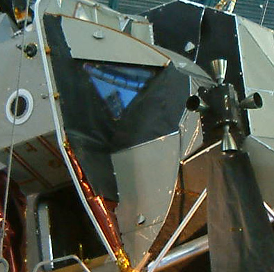
TWO DIFFERENT VIEWS - OUT THE SAME WINDOW?
Jack has shown two images, AS11-40-5847 (View out Neil's window after the landing. The foreground crater at the bottom of the image is about 10 meters in diameter. The western half of this crater is overlain by a younger, 12-m crater. Scan by Kipp Teague.) and AS11-37-5458 (View out Neil's window toward the southwest prior to the EVA. Scan courtesy NASA Johnson.).
To just look at those images, you'd have to agree with Jack. The ALSJ does indeed say they are both taken from Neil's window.
So let's take a look at an image we know was taken from Buzz's window:

AS11-37-5480
We KNOW this is taken from Buzz's window (post-EVA) because we can see the flag and the TV camera.
Now compare that to AS11-37-5458 (the correction has been made since Jack posted this study - it has been reversed to show the correct orientation):

AS11-37-5458
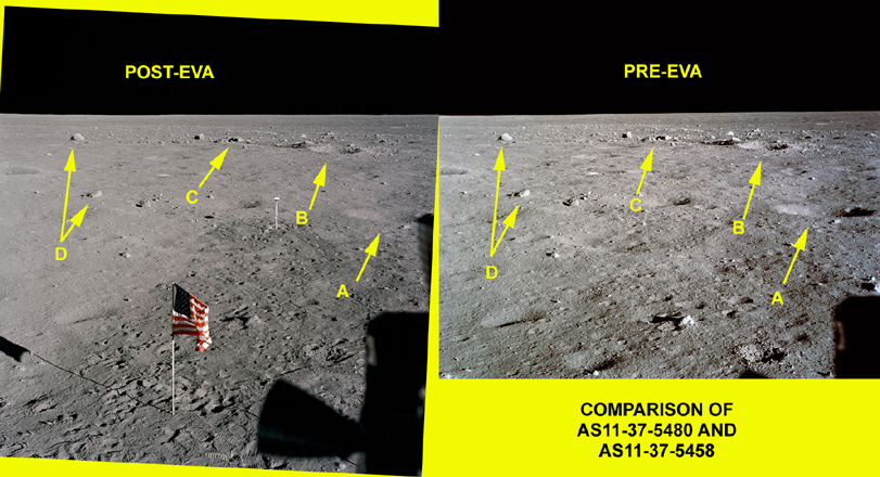
Now a comparison of the two:

COMPARISON OF AS11-37-5480 AND AS11-37-5458
So as you can see, they are of the same scene. What has happened is that the ALSJ has made a mistake (which has been reported - AGAIN) and said that AS11-37-5458 was taken from Neil's window. It was taken from Buzz's window, and the scan was accidently reversed.
It was a mistake; not anything done by "whistleblowers", just a mistake. After all, I have shown that Jack has made plenty of those so far, haven't I?
No mystery again.
-
LIGHT FROM ALL SIDES
The image Jack has posted is AS11-40-5961 .
That particular image and the effect is explained by Clavius.org here and here.
Craig has also reproduced the effect in this thread on this forum. You are strongly advised to grab a camera and reproduce a similar effect yourself.
-
SOMETHING IS OUT OF SCALE HERE - COULD THESE BE SMALL MODELS ON A MINATURE STUDIO SET?
No, they are not. Jack shows small versions of the images, and even smaller crops of other. Always look at the FULL image (especially high resolution ones, if available) to see the WHOLE scene in the best detail available.
Firstly, the main image is AS11-40-5886.
Now, in AS11-40-5875, when Buzz is saluting the flag, he is actually about 30-40cm CLOSER to the camera than the flag. If he were at the same distance, I'd expect the bottom of his shoes to be horizontal with the base of the flag (where it enter the lunar soil). They're not. They are BELOW the base. You can also see (in the high resolution version especially) that there are foot prints between the base of the flag and the horizontol level of Buzz's boots. Judging by the direction of the footprints, their angle, etc, I'd guess he was about 30-40cm closer to the camera; possibly more.
I'm willing to be corrected on the distance. If we look up how long and wide the boots were, a more precise distance could be obtained.
If we look at AS11-40-5873, when Buzz is near the Solar Wind Collector (SWC), he is actually slightly BEHIND the SWC. This may not seem much, but it's enough to cause some distortion due to perspective.
The image Jack SHOULD have used is AS11-40-5872, when Buzz is immediately next to the SWC. That would be useful to compare the heights of Buzz and the SWC.

AS11-40-5872
Next, in AS11-40-5886, the SWC is considerably FURTHER away from the camera than the flag.; I'd guess as much as a metre (again, I'm willing to be corrected).
Then there are the distances from the photographer and the subjects in each image to be considered.
So trying to compare heights is simply trying to compare apples and oranges again.
The "apparent" height difference is simply a matter of perspective, nothing more.
-
AN INCREDIBLE LIGHTING MISTAKE
In this post, Jack makes no allowance for the fact that the image is taken with the sun roughly on the right hand side. The shadow is correct, but Jack is comparing it to objects FAR in the background. You are looking at the objects at a low angle, so although the LM shadow may appear to point towards the double rock, it is not.
Let's check out the images as to what we can see clearly.
If we look at AS11-40-5931 (shown below), we can see the sun is roughly behind the LM (i.e. shining on the 'flat side' at the rear of the LM). It's not quite, because a little light is shining on the left hand side of the LM (Jack's 'side of polygon'), but it will do to illustrate that the images are correct.
So the shadow of the LM is out in 'front' of the LM. You can see the LM leg with the ladder on it is roughly in the middle of the LM shadow.

AS11-40-5931
If we look at the next image Jack has shown, AS11-40-5947 (shown below), we can see that once again the LM is lit from 'behind' (on the 'flat side'), with slightly more sun on the left hand side (the 'polygon'). We are looking the the LM roughly 'side on', and the shadow from the LM is to the left in a horizontal direction. You can see that the EASEP that Aldrin has set up also has it's shadow to the left horizontally, so we can see the sun is to the right at a roughly right angle to the direction of the photograph.

AS11-40-5947
So the lighting angle from the sun has remained the same. Jack has simply misinterpreted the images by looking at the shadows cast by near objects and comparing them to distant objects at a very low angle.
BTW, this image is a good illustration of the lunar terrain (look at the ground to the left of Aldrin) which Jack says is 'flat'.
-
BUZZ DIFFERENT IN VARIOUS IMAGES - CHECK OUT ALDRIN'S ACCOUTERMENTS
No, he is not.
1. The antenna on the PLSS backpack could be retracted. It was retracted during egress from the LM. On the surface, it was generally worn up. It was also flat, so 'side-on' it could seem to disappear but be clearly visible when seen 'front-on'.
2. The "black stripes" are the edges of the gloves (sometimes showing the glove-to-suit wrist connector) and the watch that Buzz wore.
3. The boots are always the same, as the images below show.
4. The dark grey of the gloves and boots was sometimes "washed out" in direct sunlight, and would appear to be much lighter in colour than they were. The images below also show this.
Here's an image of all the pieces that made up an astronauts suit:

The A-7L Pressure Garment Assembly courtesy of www.myspacemuseum.com
Jack shows us the following images:
AS11-40-5948 (White gloves, antenna, no wrist stripe, high boots)
AS11-40-5873 (Dark grey gloves, no antenna, no wrist stripe, high boots)
AS11-40-5868 (Dark grey gloves, antenna?, black wrist stripe, high boots)
AS11-40-5875 (White gloves, no antenna, right wrist not seen, no high boots)
AS11-40-5903 (Dark grey gloves, no antenna, possible thin wrist stripe, high boots)
AS11-40-5902 (Dark grey gloves, antenna, possible wrist stripe, high boots)
Now, here are the various images showing that there is nothing wrong and Jack has once again been mistaken:

Crop and enlargement of AS11-40-5868 showing wrist stripes

Crop and enlargement of AS11-40-5902 showing various items

Crop and enlargement of AS11-40-5903 showing wrist stripes

Crop and enlargement of AS11-40-5875 showing wrist stripes

Crop and enlargement of AS11-40-5875 showing antenna

Crop and enlargement of AS11-40-5873 showing wrist stripes

Crop and enlargement of AS11-40-5873 showing boots and washout

Crop and enlargement of AS11-40-5873 showing antenna

Crop and enlargement of AS11-40-5875 showing boots

Crop and enlargement of AS11-40-5948 showing wrist stripes
When I was looking at AS11-40-5903 (the famous Buzz photo), the NASA frame finishes at the top of the PLSS backpack so I can't look for the antenna in that image. The "black sky" has been added to the top of that image so that Buzz is more centralised in the photo, rather than right at the top.
-
ADHESIVE TAPE USED ON APOLLO 15
See previous post - Jack is not a spacecraft designer or engineer.
-
IS THIS THE LM THAT REALLY WENT TO THE MOON? CLOSE UP VIEW OF APOLLO 11 EAGLE
Well, I presume by this "article" that Jack is a spacecraft designer and engineer. He can tell you what is 'spaceworthy' and what isn't. He obviously knows how to design a lightweight spacecraft that can safely land two astronauts on the moon and return them to lunar orbit, and yet still be carried within the weight limitations of a Saturn V.
Well, Jack will tell you: he's an advertising man. He has no qualifications in aviation or engineering. I'm not a spacecraft designer or engineer, either. These people, however, are:

apmisc-LM-noID-38 courtesy of The Project Apollo Archive Image Gallery
There is no quick and easy answer to refute Jack's "expertise". You have to read about how the spacecraft was designed, built, and evolved. If you have questions, you have to address them to people who have the expertise in that area. Just because Jack cannot build a spacecraft, it doesn't mean they couldn't be built.
An excellent reference is Chariots for Apollo - A History of Manned Lunar Spacecraft .
It describes the original task, how Grumman had to design a lunar spacecraft light enough to be carried to the moon yet land it's occupants safely on the lunar surface - and return them to lunar orbit. It tells of the ingenious ways to save weight, the simplification of systems to ensure safety, the heartaches & triumphs of the design of the LM. Jack also does not mention that the Apollo 8 mission became a lunar orbital mission because the LM was not going to be ready for Earth orbit testing in time for the Apollo 8 launch - Apollo 8's original mission.
Read it.
-
CAMERA HEIGHT ANOMOLIES IN APOLLO 11 - A MATTER OF PERSPECTIVE
Let's examine some of the statements made in this claim:
1. This distant shot from Apollo 11 shows the US flag flying high above the horizon, taken with a camera at about the same height as the flag.
Firstly, let's check where the chest-mounted camera actually sat on the astronaut.

Neil Armstrong during pre-flight EVA training outside a mockup of the LM (JSC scan, AP11-S69-31054)
You can see the camera sits high on the chest, just a little underneath the visor.
Now let's compare an astronaut next to the flag.

AS11-40-5874
In this image, Aldrin is actually a little closer to Armstrong (who took the image), but it serves as an approximation. You can see that where the camera would be mounted (just under the visor) is level with the horizon in the image, which is level with the bottom of the flag.
So the camera height is about the same as the bottom of the flag if you were standing on the same level ground.
2. Note that the ground is very flat between the camera and the flag...
Actually, it's not. Have a look at some images of the ground in that area.
Firstly, the image Jack uses:

AS11-40-5950
You can see that in the area 'below' the flag and to the left, there is a crater. Further left you can see the ground rises to a lip of a crater before dropping away to a fairly deep crater (see below). 'Below' the flag and to the right, the ground rises. Just to the right of the LRRR (the white thing on the ground in the middle of the image, at about the 4 o'clock position from the flag) you can see a fairly deep depression on the ground.
Let's have a look at a cropped section of AS11-40-5950:

Cropped section (left hand side) of AS11-40-5950HR
Look under the arrows and you can see how the ground rises to the lip of a crater, before dropping off to a fairly deep crater. This is the approximate position that the second image, AS11-40-5886, was taken from. So the astronauts feet (viewed in this image) would be nearly level with the horizon - but if you look at the flag in the standard image, the base of the pole drops well below the visible horizon. AS11-40-5886 is on 'higher' ground as compared to the flag location.
So the ground is not 'very flat' - there are dips and rises everywhere. It's shown in many images, and they talk about it during the EVA:
(From the Apollo Lunar Surface Journal)
110:01:42 Armstrong: This is straight south.
110:01:45 McCandless: Roger. And we see the shadow of the LM.
110:01:48 Armstrong: Roger. The little hill just beyond the shadow of the LM is a pair of elongate craters about... Probably the pair together is about 40 feet long (east-west) and 20 feet across (north-south), and they're probably 6 feet deep. We'll probably get some more work in there later. (Pause)
[This pair of craters is shown best in the photographs taken out Neil's window. AS11-37-5452 and 5453 are good examples.]
So shots may have been taken in depressions or on rises. The interesting thing about AS11-40-5886 is that it was not taken on the RCU bracket, Aldrin removed it and took the shot of Armstrong at the LM whilst holding it in front of him:
(From the Apollo Lunar Surface Journal)
Buzz's Plus-Z Pan (frames 5881 to 5891)
[Aldrin, from the 1969 Technical Debrief - "I took the first panorama out in front without having the camera mounted on the RCU, and it did not appear to be unnatural to do so. It's much easier to operate with it mounted; however, I didn't find that the weight of the camera was as much a hindrance to operation as pre-flight simulations indicated it would be. There is no doubt that having the mount frees you to operate with both hands on other tasks. The handle is adequate to perform the job of pointing the camera. I don't think we took as many inadvertent pictures as some pre-flight simulations would have indicated. It seems as though, in all the simulations where we picked up the camera, we always managed to take (unintended) pictures. I don't think that was the case in this mission as much as we thought it was going to be. We'll know if a number of pictures taken are pointed at odd angles."]
That the images show the flag above the lunar horizon in one image and in the middle of it in another prove absolutely nothing.
There is also an excellent geologic map of the Apollo 11 landing site in the ALSJ, which shows locations of the main craters, where and in what direction certain images were taken, etc, and links to those images. A very handy resource.
-
USE OF TRIPOD ON THE MOON? 1
Before looking at the images, let's review what Jack has said:
1. These two new images appear identical except for a couple of minor details you can see. They are said to be consecutive exposures made by "Armstrong" of "Aldrin" descending from the LEM.
The images are cropped from AS11-40-5867 and AS11-40-5868, which are consecutive images.
2. These IDENTICAL LINES OF SIGHT CAN BE ACHIEVED ONLY WITH A TRIPOD.
Absolute bunkum. Firstly, they are NOT identical (which I'll show shortly), and secondly they could be achieved without a tripod. All it requires is to remain still between shots.
3. But the alleged camera was a CHEST-MOUNTED Hasselblad attached to the "Armstrong" chest, and he was moving around, and his camera HAD NO VIEWFINDER. How did he mange to expose, wind film, and take the next shot FROM THE EXACT SAME POINT OF VIEW?
To begin, Jack actually has something right - there was no viewfinder. What he wants you to believe, though, is that the camera was something like you would use to take 'happy snaps'.
Now - prove that he was moving around, Jack. You have evidence that he did? Did he go for a walk, dance a little jig, play a round of golf? The shots were CONSECUTIVE, one taken immediately after the other.
The Hasselblad was activated by either a button the front of the camera, or when chest mounted, by squeezing a trigger on the grip that was attached to the camera.


Images of Hasselblad camera courtesy of www.myspacemuseum.com
Information on the Hasselblad camera used on the lunar surface.
The camera had an electric winder to move to the next frame.
So it was very easy to take two consecutive shots from the same viewpoint. You stay still, CLICK, wait for the frame advance, CLICK.
Let's look at the two images Jack has shown:

AS11-40-5867

AS11-40-5868
Gee, it looks to me that if this were taken with a tripod, they must have moved the tripod a bit.
There is an obvious difference between the images. The photographer, Neil Armstrong (NOT alleged), has moved his body very slightly. You can see this, even in Jack's cropped images, because the lens flare at the bottom right of the picture has moved slightly.
If you can't see it with the large images, try going to The Project Apollo Image Gallery and look up the two images. You can see them in a smaller scale, and the movement becomes more apparent.
The cropped images show practically no difference in viewpoint because there was very little movement between the shots.
Once again, there are NO problems with the images.


Jack White's Aulis "Apollo Hoax" Investigation - A Rebuttal
in The Apollo Moon Landings
Posted
WERE LUNAR AERIAL SURFACE PHOTOS MADE USING LARGE SCALE MODELS?
I'm not quite sure what point Jack is trying to make here.
As soon as a lunar landing became a goal of the US space programme, they had to do research. They had to find out what the moon was really like. The constraints upon a lunar lander would not allow it to flitter above the lunar surface, looking for a nice spot to land. All available information had to be gathered in order to determine the best spot to land.
In order to gather this information, NASA launched the Ranger, Lunar Orbiter, and the Surveyor probes.
The Lunar Orbiter's were designed to take detailed images of the lunar surface until a hard impact on the surface (destroying the probe). The Surveyor probes were designed to make a soft landing on the lunar surface, determine what the surface was, and take detailed images of it.
See here for some history of those flights.
These (along with released images of Soviet lunar probes) were used to create detailed maps and models of the moon. When Apollos 8 and 10 also went into lunar orbit, one of their primary concerns were to make detailed studies of the lunar surface. This data was also used in the construction of models and selection of the Apollo 11 landing site.
These models were not only used for site selection, they were used for training the astronauts as well. Simulators were still fairly primitive in those days, so when the astronauts practiced lunar orbit and landing sequences, the models were used. A television camera was aimed at the models to help the astronauts become familiar with the features and terrain they would be expecting. The LM simulator did not "generate" images , it relied on models.
It's just another part of the Apollo programme - practice, practice, practice.